Sunday, July 27, 2014

Nodal Analysis


Nodal analysis is a systematic method to determine the voltage at each node relative to the reference node by repeatedly applying KCL. In Nodal analysis, also called node-voltage analysis or branch current method, the voltage between nodes is determine in terms of the branch currents. In this method a system of equations in which the unknowns are the voltages at the principal node of the circuit is set up and solve. The set of equation develops in the nodal analysis in fact represents and describes the circuit. After determining these nodal voltages, the currents in the various branches of the circuit can be easily found.

The procedure for nodal analysis can be divided into three basic steps:

  1. Label the node voltage with respect to the reference node
  2. Apply KCL to each of the nodes in terms of the node voltages.
  3. Determine the unknown node voltages by solving the simultaneous equations from step 2.

For example,

Use Nodal analysis to find the voltage at each node of this circuit


Solution:

  • Note that the "pair of nodes" at the bottom is actually 1 extended thus the number of nodes is 3.
  • We will number the nodes as shown in figure below.
  • We will chose node 2  as the reference node and assign it a voltage of zero.
  • Write down Kirchoff's Current Law for each node. Call V1 the voltage at Node 1, V3 the voltage at Node 3, and remember that V2 = 0. The result is the following system of equations:
The first equation result from KCL applied at node 1 and the second equation results from KCL applied at node 3. Collecting terms this becomes:


This form for the system of equations could have been gotten immediately by using the inspection method

Solving the system of equation using Gaussian elimination or some other method gives the following voltages:

V1 = 68.2 volts  and   V3 = 27.3 volts


Saturday, July 12, 2014

Series & Parallel Circuit

Series Circuits
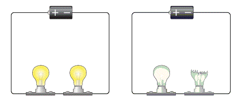
Series circuits are sometimes called current-couple or daisy chain-coupled. The current in a series circuit goes through every components in the circuit. Therefore, all of the components in a series connection carry the same current. there is only one path in a series circuit in which the current can flow. A simple circuit has one power source and one output device. Simple circuit are limited in the amount of power that can be provided. It uses a single path to connect all devices.

Simple Series Circuit

Advantage and Disadvantage
An advantage of a series circuit is that you can add more power devices, such as more batteries, and increase the force of the output. This will give your more power. 
One disadvantage is that as you add output devices, such as light bulbs, you increase the resistance and the bulbs do not shine as brightly. Another important disadvantage is that if one output devices stops working, all the other output devices will stop working too. This is because all of the power and output devices are connected in a straight line. When one fails, you have broken circuit and nothing will work.


Parallel Circuit

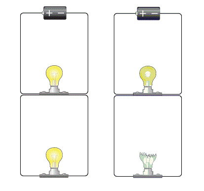
If two or more components are connected in parallel they have the same potential difference (voltage) across their ends. The potential differences across the components are the same magnitude, and they also have identical polarities. The same voltage is applicable to all circuit components connected in parallel. The total current is the sum of the currents through the individual components, in accordance with Kirchoff's current law.

Simple Parallel Circuit


Advantage and Disadvantage

Parallel circuit also have more than one power source or output device. They use more than one path for the electricity to flow. You can think of a parallel device as having a main line going out from the power source and another main line going back to it. The output devices use branch line to connect each of their positive poles to one main line and their negative poles to the other main line. The advantage of a parallel circuit is that if one of the output devices burns out, then only that device stops working. The disadvantage is that if you have multiple power source, the power stays at the same voltage as that of the single power source. But in parallel circuit increasing the number of output devices does not increase the resistance the way it does in series circuits.


Learnings:

In this topic, we discuss the series and parallel circuit. I've learned that the series circuit has only one path to follow. If the circuit is open, or broken, at any point, current stops flowing through every part of the circuit. For example, strings of tree light used to be wired in series. When one bulb burned out, the circuit was broken. As a result, the current would stop and all of the bulb would go out. While in the parallel circuit even if one of the branches of the circuit is broken, current still flows though the rest of the circuit. 


“Enthusiasm is the electricity of life. How do you get it? You act enthusiastic until you make it a habit.” 


Saturday, July 5, 2014

Nodes, Branch and Loops

Nodes
A point or junction where two or more circuit's elements (resistor, capacitor etc.) meet is called Node.

Branch
That part of section of circuit which locate between two junctions is called branch. In branch, one or more elements can be connected and they have two terminals.

Loop
Is any close path in the circuit.Loop counts starting at a node passing through a set of nodes and returning to the starting node without passing through any node more that once.


Kirchoff's Current Law (KCL)

This law is also called Kirchhoff's first lawKirchhoff's point rule, or Kirchhoff's junction
rule (or nodal rule).
The principle of conservation of electric charge implies that:
At any node (junction) in an electrical circuit, the sum of currents flowing into that node is equal to the sum of currents flowing out of that node, or:
The algebraic sum of currents in a network of conductors meeting at a point is zero.


Kirchoff's Voltage Law (KVL)

This law is also called Kirchhoff's second lawKirchhoff's loop (or mesh) rule, and Kirchhoff's second rule.
The principle of conservation of energy implies that. The directed sum of the electrical potential differences (voltage) around any closed network is zero, or:
More simply, the sum of the emfs in any closed loop is equivalent to the sum of the potential drops in that loop, or:
The algebraic sum of the products of the resistances of the conductors and the currents in them in a closed loop is equal to the total emf available in that loop.


"There must be a positive and negative in everything in the universe in order to complete a circuit or circle, without which there would be no activity, no motion"
- John McDonald