Capacitors are components designed to take advantage of this phenomenon by placing two conductive plates (usually metal) in close proximity with each other. There are many different styles of capacitor construction, each one suited for particular ratings and purposes. For very small capacitors, two circular plates sandwiching an insulating material will suffice. For larger capacitor values, the "plates" may be strips of metal foil, sandwiched around a flexible insulating medium and rolled up for compactness. The highest capacitance values are obtained by using a microscopic-thickness layer of insulating oxide separating two conductive surfaces. In any case, though, the general idea is the same: two conductors, separated by an insulator.
The schematic symbol for a capacitor is quite simple, being little more than two short, parallel lines (representing the plates) separated by a gap. Wires attach to the respective plates for connection to other components. An older, obsolete schematic symbol for capacitors showed interleaved plates, which is actually a more accurate way of representing the real construction of most capacitors:

When a voltage is applied across the two plates of a capacitor, a concentrated field flux is created between them, allowing a significant difference of free electrons (a charge) to develop between the two plates:

As the electric field is established by the applied voltage, extra free electrons are forced to collect on the negative conductor, while free electrons are "robbed" from the positive conductor. This differential charge equates to a storage of energy in the capacitor, representing the potential charge of the electrons between the two plates. The greater the difference of electrons on opposing plates of a capacitor, the greater the field flux, and the greater "charge" of energy the capacitor will store.
Just as Isaac Newton's first Law of Motion ("an object in motion tends to stay in motion; an object at rest tends to stay at rest") describes the tendency of a mass to oppose changes in velocity, we can state a capacitor's tendency to oppose changes in voltage as such: "A charged capacitor tends to stay charged; a discharged capacitor tends to stay discharged." Hypothetically, a capacitor left untouched will indefinitely maintain whatever state of voltage charge that its been left it. Only an outside source (or drain) of current can alter the voltage charge stored by a perfect capacitor:

Practically speaking, however, capacitors will eventually lose their stored voltage charges due to internal leakage paths for electrons to flow from one plate to the other. Depending on the specific type of capacitor, the time it takes for a stored voltage charge to self-dissipate can be a long time (several years with the capacitor sitting on a shelf!).
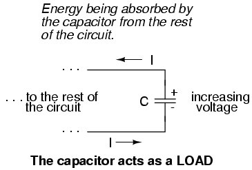
When the voltage across a capacitor is increased, it draws current from the rest of the circuit, acting as a power load. In this condition the capacitor is said to becharging, because there is an increasing amount of energy being stored in its electric field. Note the direction of electron current with regard to the voltage polarity:
Conversely, when the voltage across a capacitor is decreased, the capacitor supplies current to the rest of the circuit, acting as a power source. In this condition the capacitor is said to be discharging. Its store of energy -- held in the electric field -- is decreasing now as energy is released to the rest of the circuit. Note the direction of electron current with regard to the voltage polarity:

.
An obsolete name for a capacitor is condenser or condensor. These terms are not used in any new books or schematic diagrams (to my knowledge), but they might be encountered in older electronics literature. Perhaps the most well-known usage for the term "condenser" is in automotive engineering, where a small capacitor called by that name was used to mitigate excessive sparking across the switch contacts (called "points") in electromechanical ignition systems.
No comments:
Post a Comment